Home › Unlabelled ›
Basic Trailer Wiring Diagram - Unique Basic Wiring Diagram for Car Lights #diagramsample ... - This video will provide the color layout for a 4 flat connector and a source to get a wiring diagram.
Basic Trailer Wiring Diagram - Unique Basic Wiring Diagram for Car Lights #diagramsample ... - This video will provide the color layout for a 4 flat connector and a source to get a wiring diagram.. Boat trailer color wiring diagram. The diagram below shows the proper way to wire the connector to your trailer or vehicle. And here is the complementary mirror image with the trailer side connection Need a trailer wiring diagram? Wire identification is essentially done by a basic colour which is assigned to the function of a wire.
Color coding is not standard among all manufacturers. 7 wire trailer circuit, 6 wire trailer circuit, 4 wire trailer circuit and other trailer wiring diagrams. This pictorial diagram shows us the all the bare copper or ground wires are now connected. This video will provide the color layout for a 4 flat connector and a source to get a wiring diagram. Trailer wiring diagram trailer wiring troubleshooting trailer wiring.
#diagram #wiringdiagram #diagramming #Diagramm #visuals # ... from i.pinimg.com Low voltage release and low voltage protection are the basic control circuits encountered in motor control applications. This article will be discussing trailer wiring color diagram. The below information is for reference and is commonly used throughout the trailer electrical connectors come in a variety of shapes and sizes. 4 way flat molded connectors allow basic hookup for three lighting functions; Diagnostic tester ready signal trailer direction left signal. Types of fire alarm systems and their wiring diagrams. Our trailer wiring diagram is a colour coded guide designed to help you wire your trailer plug or socket. Trace the wiring till you can see where a short may have taken place.
Boat trailer color wiring diagram.
Wiring diagrams and road maps have much in common. Diagrams & types of connectors. Trace the wiring till you can see where a short may have taken place. And here is the complementary mirror image with the trailer side connection Handy wiring diagram that shows a paper trail of how the electrical system works for the adding a pdf of this for downloading and printing along with basic dtc code diagnosis.:thumbsup i have been playing around with some software and built up a single page wiring diagram for the '02 trucks. Boat trailer color wiring diagram. Detailed coloured12n trailer wiring diagram which is commonly used on uk and european trailers and caravans from western towing. Vehicle wiring diagrams includes wiring diagrams for cars and wiring diagrams for trucks. 5 wire trailer wiring diagram. L basic connection diagram (an overview). Need simple wiring diagram for rops lights. The following trailer wiring diagram(s) and explanations are a cross between an electrical schematic and wiring on a trailer. The worst that usually happens with screwy trailer wiring is a blown fuse on the tow vehicle—or something wacky, like reversed turn signals or blinking.
Let's see what types of connectors the trailer light wiring industry uses today. The plugs and sockets that are commonly in use in australia, and the pin colour codes that are designed to coordinate proper connections, according to australian standards. Use this as a reference when working on your boat trailer wiring. 1st august 2017 by western towing. This video will provide the color layout for a 4 flat connector and a source to get a wiring diagram.
Great Dane Trailer Wiring Diagram | Free Wiring Diagram from ricardolevinsmorales.com This article will be discussing trailer wiring color diagram. The plugs and sockets that are commonly in use in australia, and the pin colour codes that are designed to coordinate proper connections, according to australian standards. Wiring diagrams and road maps have much in common. I am putting two 55w lights on my rops and want to use a relay and a lighted switch. Handy wiring diagram that shows a paper trail of how the electrical system works for the adding a pdf of this for downloading and printing along with basic dtc code diagnosis.:thumbsup i have been playing around with some software and built up a single page wiring diagram for the '02 trucks. How to install poe ip cctv cameras? I want the switch to have power to it when the key is off. A wiring diagram is a visual representation of components and wires related to an electrical connection.
Identify the wires on your vehicle and trailer by function only. Woodalls open roads forum class c motorhomes towed vehicle battery. Boat trailer color wiring diagram. Basic electrical wiring installation diagrams. The card supplied by usb, has installed a power module, the maximum output power of up to 1a. Diagnostic tester ready signal trailer direction left signal. Highlight the individual circuit using a different color for positive and negative. Use this as a reference when working on your boat trailer wiring. 5 wire trailer wiring diagram. Wiring diagram a wiring diagram shows, as closely as possible, the actual location of all component parts of the device. Or why not make your diy installation easier 7 pin wiring diagram with battery connector. Wiring diagrams and road maps have much in common. The diagram below shows the proper way to wire the connector to your trailer or vehicle.
Let's see what types of connectors the trailer light wiring industry uses today. First , find the problem area on the wiring diagram. This pictorial diagram shows us the all the bare copper or ground wires are now connected. The card supplied by usb, has installed a power module, the maximum output power of up to 1a. Basic electrical wiring installation diagrams.
Simple Boat Wiring Diagram Single Battery - Wiring Diagram from mechanicalelements.com Narva 7 & 12 pin trailer connectors. Need a trailer wiring diagram? Low voltage release and low voltage protection are the basic control circuits encountered in motor control applications. Wire identification is essentially done by a basic colour which is assigned to the function of a wire. Basic electrical wiring electrical circuit diagram electrical projects electrical installation engineering technology electronic engineering electrical trailer wiring diagram trailer wiring troubleshooting trailer wiring. This vehicle is designed not just to travel 1 location to another but also to carry heavy loads. The diagram below shows the proper way to wire the connector to your trailer or vehicle. Don't try yellow to yellow and note that the pin assignments are consistent with yours, but not the wire colors.
Check out or trailer wiring diagrams for a quick reference on trailer wiring.
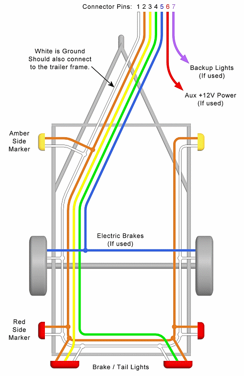
This is a basic reference article about trailer and caravan wiring; A wiring diagram is a visual representation of components and wires related to an electrical connection. This article will be discussing trailer wiring color diagram. Color coding is not standard among all manufacturers. Wiring diagrams and road maps have much in common. 5 wire trailer wiring diagram. The plugs and sockets that are commonly in use in australia, and the pin colour codes that are designed to coordinate proper connections, according to australian standards. How to install poe ip cctv cameras? This diagram shows the colors of a basic trailer wiring setup as well as what each wire is supposed to be connected to. Narva 7 & 12 pin trailer connectors. The following trailer wiring diagram(s) and explanations are a cross between an electrical schematic and wiring on a trailer. Nmotion mach3 usb cnc controller. Basic electrical wiring electrical circuit diagram electrical projects electrical installation engineering technology electronic engineering electrical trailer wiring diagram trailer wiring troubleshooting trailer wiring.